USB-IR-Boy Board
Parts list
- one 20-pin PDIP case Freescale MC68HC908, part code MC68HC908JB8JPE
- one 10 MOhm resistor
- one 6 Mhz crystal
- two 22 pF capacitors
- one TSOP1738 (or compatible IR receiver, e.g. SFH506-38)
Unspecified parts
- R1 is a 110 - 162 kOhm resistor for voltage deviation to MCU pin (100k gives about 4V and 162k about 2.4V). I use 110k to get about 3.6V. (This depends on Vcc, reference is 5V as it should be). Make sure the voltage does not go above the maximal rating of 3.6V!
- C1 is a capacitor to stabilize the USB provided power. Reception of the TSOP is poor without it, and it should be as big as possible. The TSOP data sheet suggests 4.7 uF. I use 100 nF. The capacitor should be located near the power pins of the TSOP.
Electronic schematic
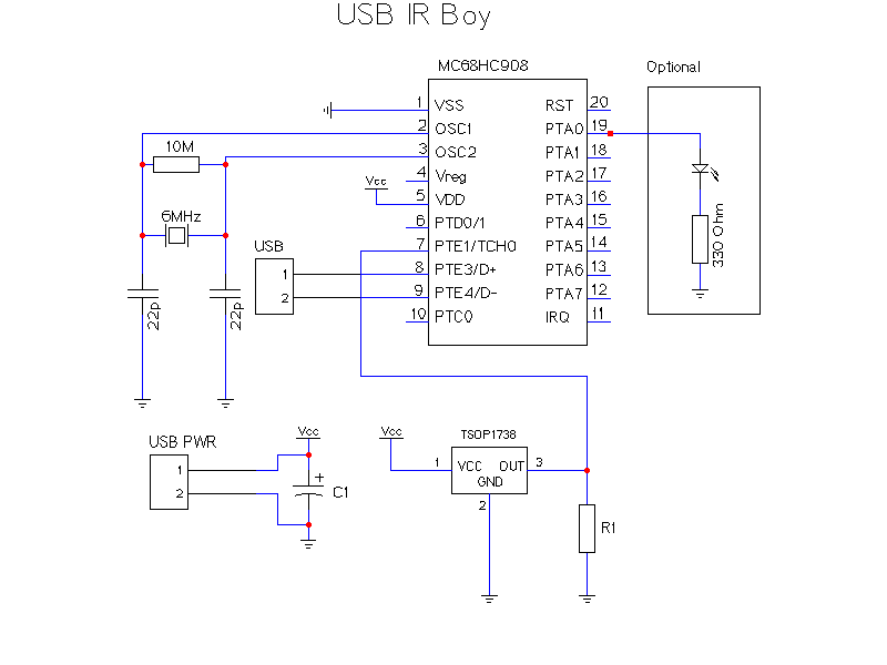
The following image shows the electronic schematic of the USB-IR-Boy device board.
There is also an optional LED connected to PTA0 which in the MCU code is toggled on and off during the execution of the program. The LED can be used to ensure your circuit is working and the MCU software is running correctly.

Created with gEda (Printer-friendly version)
Notes
- Vcc is 5V (provided from the USB connector)
- The R1 resistor is there to make voltage deviation from 5V to the MCU input level of 3.3V. The TSOP1738 has an internal pullup resistor of 80kOhm between pin 3 and Vcc.
- MCU PTA,RST,PTD0/1 and IRQ pins are "in the air" since they have internal pullups.
- There is no resistor between the MCU D- and Vdd pins since there is an internal pull-up resistor (enabled by the usb_init function).
- The USB internal power source can be used but it might decrease the sensibility of the TSOP due to the strict operating voltage stability it needs.
- USB PWR and USB connectors can be chosen separately or to use the same connector depending on the board layout. There are also standard USB connectors that can be used but they are not needed for home use. (Some say this is adviced since it makes the USB side of the system more stable.)
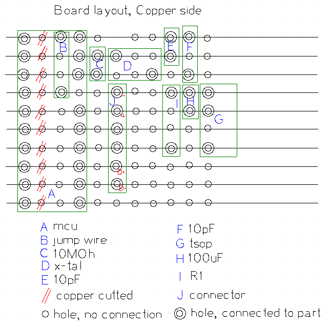
"Mini" stripboard layout
The following image shows an example design using a stripboard. Please see the pictures section for an implemented board using this layout.

Printer-friendly version available
Notes
- Picture is taken from the solder (copper) side of the board
- MCU pin 20 is in the picture upper left corner
- MCU pin 4 is not connected to the board (chip socket pin 4 must be cut so it does not touch the copper lines on the board!)