Prommer
Parts list
- one 16-pin PDIP case Maxim MAX232(A) (RS232 driver), e.g. MAX232ACPE
- four 10 kOhm resistors
- one 2.2 kOhm resistor
- one 10 MOhm resistor
- one 6 Mhz crystal
- two 22 pF capacitors
- four 100 nF capacitors
- one fast (Schottky) diode, e.g. BAT42 or 1N5818
- RS232 connector, female, 9-pin (check your serial cable)
- one 20-pin DIL socket for the MCU (ZIF if you can afford it)
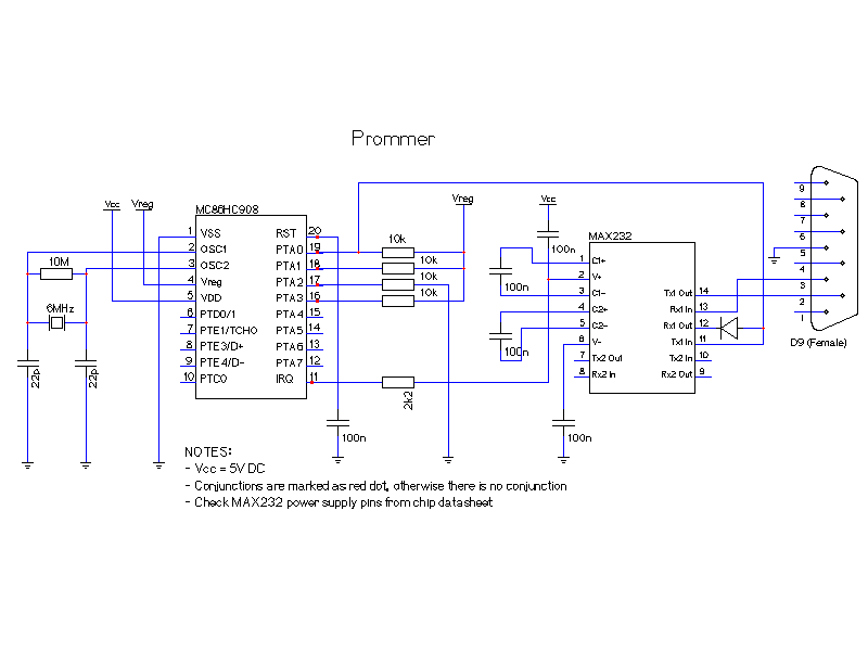
Electronic schematic
The following electronic schematic shows the home made prommer which we have been using to program the MCU.

Created with gEda (Printer-friendly version)
Notes
- Vcc is 5V
- Vreg is an 3.3V output regulated by the MCU
- The MAX232 power pins are not shown in the schematic due to the way gEda handles default chip power pins. (VCC=pin 16, GND=pin 15)
Pimp my prommer!
Kustaa Nyholm has a few more components on his board at his Fun with HC08 page which can turn your prommer board into a minimal "development" board. This is very handy if you work on the MCU code and want to try it out without taking the MCU out of the prommer and into your "production" board.
- With one LED, one 390 Ohm resistor and some wire you can have a LED logically tied to the PTA0 port. The LED will also flash quickly when you are programming the MCU.
- With one NPN transistor (BC547, 2N3904 or similar) and a 10 kOhm and a 2.2 kOhm resistor you can reset the MCU from the computer by raising DTR on the serial port. The bl08 prommer software can do this for you with the -r option.
- If you want to hook up the USB port, connect two 27 Ohm resistors to PTE3 and PTE4 on the MCU. No pull-up resistor is needed.
See the "Full schematics" on his web site for more details.